|
Hello ! Yup, it's us again !  If you're into maths, this post might interest you; it is about the DLT method. Wait, what is the DLT method you say ? Why do we want to discuss about it ? DLT stands for Direct Linear Transformation method. It is used to calibrate cameras, such as the ones Hanaé is handling during her internship, to convert 2D positions from 2D frames back into real 3D positions, and so track precisely the red nose tetra fish in her experiment. This technical report [7] and this website [8], explain it clearly. But we still think it is complex to understand... Therefore, here, we will report simply the DLT method demonstrated in [7] and [8], by applying it to Hanaé's experiment.
The DLT method uses this set of control points, whose 2D image space coordinates are known, to calculate the mapping between them and the 3D object space coordinates.
Considering [u0, v0, 0], the principal point’s coordinates, the image reference coordinates of C become then [u0, v0, d], and the vector V2 drawn from C to I is then [u-u0, v-v0, -d]. Since O, I and C are collinear, vector V1 and V2 form a single straight line and V2 = cV1. (with c a scaling scalar). Note here that vectors V1 and V2 were originally described in the object-space reference frame and in the image-plane reference frame respectively. In order to directly relate the coordinates, the DLT method necessary describes them in a common reference: so vector V1 is then transformed to the image-plane reference frame.
Now the system can replace V1 and V2 in the expression: V2 = cV1, regarding the vectors in the image-plane reference frame: 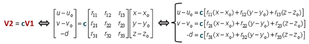
Which is then used to substitute c in the first two above expressions:
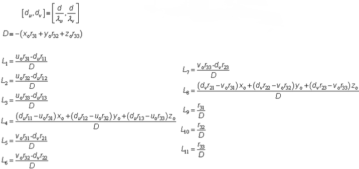 Coefficients L1 to L11 are the two side DLT cameras’ parameters Hanaé obtains with the calibration MATLAB code, that reflect the relationships between the object-space reference and the image-plane reference. Thanks to them, 2D image-space coordinates, can be projected into 3D object-space coordinates, and vise versa, when the points considered are visible from both cameras. This is called reconstruction using DLT method. REF: [7] Article: Bardsley & Li - 3D Reconstruction Using the Direct Linear Transform with a Gabor Wavelet Based Correspondence Measure: http://bardsley.org.uk/wp-content/uploads/2007/02/3d-reconstruction-using-the-direct-linear-transform.pdf [8] Website: Kwon - 1998 - DLT Method - website: http://www.kwon3d.com/theory/dlt/dlt.html [9] Article: Abdel-Aziz & Karara - 1971 - Direct linear transformation into object space coordinates in close range photogrammetry - ASP Symposium on Close-Range Photogrammetry in Illinois, Pages 1-18.
3 Comments
Maryam
6/11/2016 07:55:07 am
Ouuu this was a little bit complicated ! Yet, I find that you pretty well explained these complicated concepts. If I understood correctly, all these calculations lead to parameters (that you find with MATLAB ?) which are then entered somehow into your cameras. And that way, the cameras with the parameters "inside of them" are able to convert (automatically ?) 2D positions into 3D ones which gives more accurate data ... Is that right ?
Hanae
7/11/2016 03:03:08 am
Yes, that is all correct ! I'm glad yo could understand the concept. And yes it is with MATLAB that we calculate the DLT coefficients. These parameters are then entered in another MATLAB code, a code which tracks the 2D fish's positions (U,V) from frames, to convert them automatically in 3D positions (X,Y,Z).
Maryam
7/11/2016 10:48:43 am
OK it is clearer now. Thank you for teaching me the basics of the DLT method ! Leave a Reply. |
Search the site...
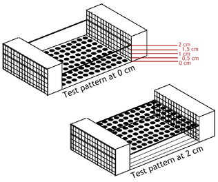


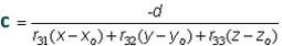
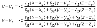
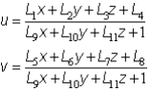
Photo used under Creative Commons from DJANDYW.COM & DJANDYW.TV AKA ANDREW WILLARD
